|
The 555 astable circuit provides clock pulses for the 4017 counter which has ten outputs (Q0 to Q9). Each output becomes high in turn as the clock pulses are received. Appropriate outputs are combined with diodes to supply the amber and green LEDs. The red LED is connected to the ÷10 output which is high for the first 5 counts (Q0-Q4 high), this saves using 5 diodes for red and simplifies the circuit.
This project uses a 555 astable circuit to provide the clock pulses for the 4017 counter.
Parts Required
- resistors: 470 ×3, 22k, 100k
- capacitors: 0.1µF, 1µF 16V radial, 10µF 16V radial
- diodes: 1N4148 ×6
- LEDs: red, amber (or yellow), green
- 1M preset, horizontal
- 555 timer IC, such as NE555
- 4017 counter IC
- DIL sockets for ICs: 8-pin, 16-pin
- on/off switch
- battery clip for 9V PP3
- stripboard: 20 rows × 21 holes
Stripboard Layout

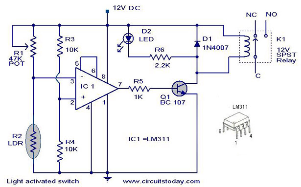
Circuit diagram